Load balancing Hyland Enterprise Imaging
Updated on November 25, 2025
•
Published on March 7, 2023
Benefits of load balancing Hyland Enterprise Imaging
Load balancing is critical for medical imaging systems like Hyland Enterprise Imaging for the following reasons:
- Enhanced Performance (Speed and Responsiveness): Load balancing significantly improves system speed, which is crucial for large medical imaging files (CT, MRI, X-Ray). It distributes the high volume of incoming traffic (like DICOM studies and image retrieval requests) across multiple servers. This prevents any single server from becoming overwhelmed. By routing requests to the least busy or most available server, it ensures rapid processing and retrieval of images. This leads to faster response times for clinicians and radiologists, improving workflow and decreasing turnaround times for reports.
- High Availability (HA): In a 24/7 patient care environment, continuous access to critical images can be life-saving. A load balancer constantly monitors the “health” of all image servers (e.g., PACS or VNA servers). If one server fails or experiences degradation, the load balancer automatically and seamlessly redirects all traffic to the remaining healthy servers. This eliminates single points of failure, ensuring continuous, uninterrupted access to diagnostic images and patient data, minimizing disruptions to clinical workflows.
- Scalability for future growth: Load balancing provides the flexibility to handle the constantly increasing volume of medical data and user demands without interruption. As the volume of imaging data grows (which it does rapidly in healthcare), new servers can be added to the cluster without taking the system offline. The load balancer automatically incorporates these new servers into the distribution pool, allowing the system to scale its capacity out and handle the increased workload, future-proofing the platform for long-term data growth.
About Hyland Enterprise Imaging
Hyland delivers enterprise image connectivity solutions, enabling users to capture, store, manage and share clinical documents, photos and video. Hyland systems enable the integration of all medical imaging content types – including DICOM, XDS and non-DICOM – with existing EMR and PACS imaging archives.
For caregivers to work effectively, peak performance of Hyland applications is crucial. Doctors demand instant image and data retrieval, zero downtime, and systems which are easy to maintain with simple security updates.
Clustering multiple load balanced Hyland servers provides product managers with a fast, cost-effective, highly available and scalable solution, in an environment where study volume is ever increasing.
Why Loadbalancer.org for Hyland Enterprise Imaging?
Loadbalancer’s intuitive Enterprise Application Delivery Controller (ADC) is designed to save time and money with a clever, not complex, WebUI.
Easily configure, deploy, manage, and maintain our Enterprise load balancer, reducing complexity and the risk of human error. For a difference you can see in just minutes.
And with WAF and GSLB included straight out-of-the-box, there’s no hidden costs, so the prices you see on our website are fully transparent.
More on what’s possible with Loadbalancer.org.
How to load balance Hyland Enterprise Imaging
The load balancer can be deployed in 4 fundamental ways: Layer 4 DR mode, Layer 4 NAT mode, Layer 4 SNAT mode, and Layer 7 Reverse Proxy (Layer 7 SNAT mode).
For Hyland Enterprise Imaging, Layer 7 Reverse Proxy is recommended.
Virtual service (VIP) requirements
To provide load balancing and HA for Hyland OnBase, multiple Web Servers and Application Servers are load balanced and the following VIPs are required:
| Ref. | VIP Name | Use | Mode | Port(s) | Persistence Mode | Health Checks |
|---|---|---|---|---|---|---|
| VIP 1 | WebServers | Web Server traffic | Layer 7 Reverse Proxy | 80 | HTTP Cookie | HTTP (GET) |
| VIP 2 | AppServers | App Server traffic | Layer 7 Reverse Proxy | 80 | HTTP Cookie | HTTP (GET) |
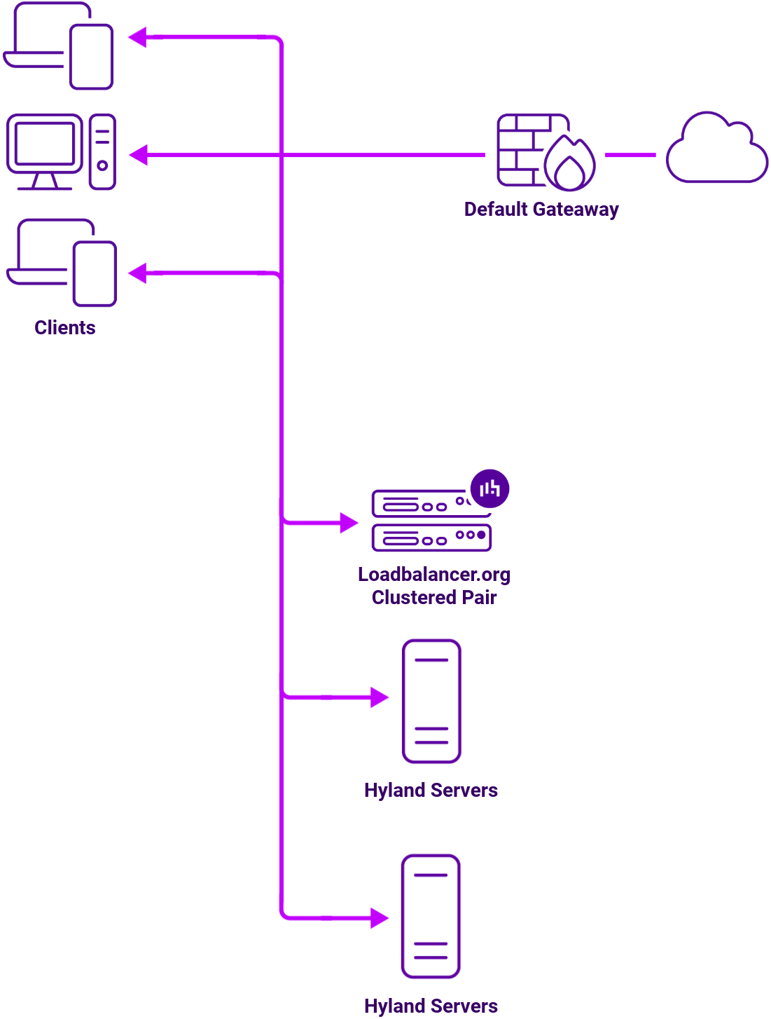
Load balancing deployment concept
About Layer 7 Reverse Proxy load balancing
Layer 7 Reverse Proxy uses a proxy (HAProxy) at the application layer. Inbound requests are terminated on the load balancer and HAProxy generates a new corresponding request to the chosen Real Server. As a result, Layer 7 is typically not as fast as the Layer 4 methods.
Layer 7 is typically chosen when enhanced options such as SSL termination, cookie based persistence, URL rewriting, header insertion/deletion etc. are required, or when the network topology prohibits the use of the Layer 4 methods.

Because Layer 7 Reverse Proxy is a full proxy, any server in the cluster can be on any accessible subnet, including across the Internet or WAN.
Layer 7 Reverse Proxy is not transparent by default i.e. the Real Servers will not see the source IP address of the client, they will see the load balancer’s own IP address by default, or any other local appliance IP address if preferred (e.g. the VIP address). This can be configured per Layer 7 VIP.
If required, the load balancer can be configured to provide the actual client IP address to the Real Servers in two ways:
- Either by inserting a header that contains the client’s source IP address, or
- By modifying the Source Address field of the IP packets and replacing the IP address of the load balancer with the IP address of the client.
Layer 7 Reverse Proxy mode can be deployed using either a one-arm or two-arm configuration. For two-arm deployments, eth0 is normally used for the internal network and eth1 is used for the external network, although this is not mandatory.
No mode-specific configuration changes to the load balanced Real Servers are required.
Port translation is possible with Layer 7 Reverse Proxy e.g. VIP:80 → RIP:8080 is supported. You should not use the same RIP:PORT combination for Layer 7 Reverse Proxy VIPs and Layer 4 SNAT mode VIPs because the required firewall rules conflict.